Central passage
The bore diameter is assessed against the dimensions of the shaft or component that needs to pass through.
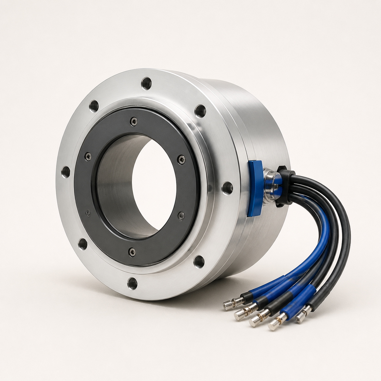
Core Slip / 02 — Integrated through-bore
Passage at the centre. Connection around it. A hollow-shaft design combines power and signal transmission on the same axis while preserving your mechanical layout.
When a shaft or another component must pass through the centre, the slip ring architecture takes shape around it. Bore diameter and mounting dimensions are the starting point.
The bore diameter is assessed against the dimensions of the shaft or component that needs to pass through.
Flanges, housing and mounting points are planned around the rotating mechanism's layout.
Power, control and data requirements are considered alongside the available space and operating speed.
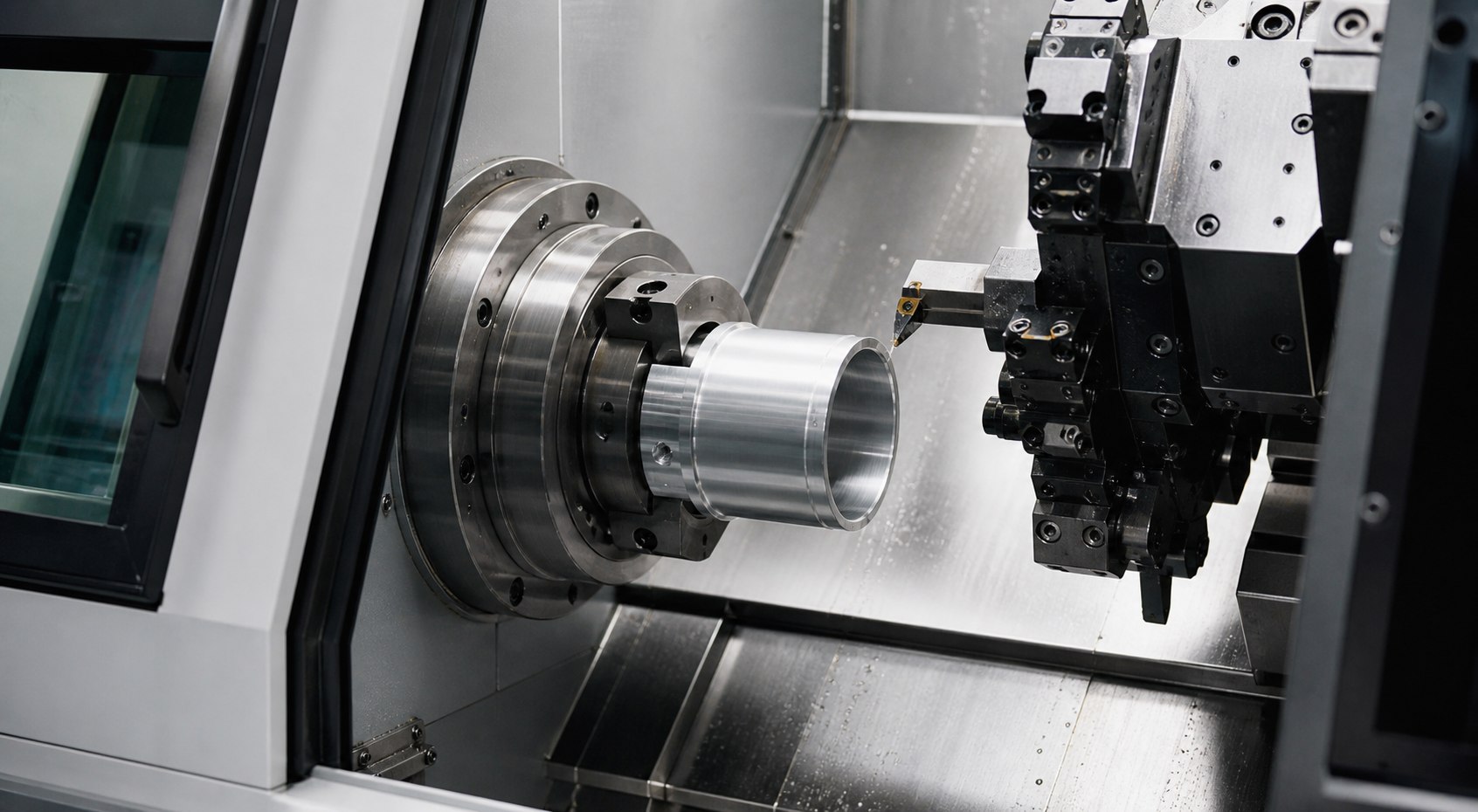
Precision machining
A larger central passage is not enough on its own. Mounting tolerances, bearings, cable directions and service access are considered together to define the housing geometry.
Dimensions and performance values are defined by project requirements; this product family is not limited to a single standard size.
Product selection considers mechanical layout, transmission needs and operating conditions together.
A through-bore slip ring leaves a central passage for a shaft or a suitable application line. This opening defines the mechanical layout around which electrical channels are arranged. Outside diameter, axial length and mounting method matter as much as the required bore size. The movement of the part passing through the centre must be reviewed together with slip ring rotation.
A drawing showing shaft diameter, installation clearance and mounting points helps the review. Describe power and data channels separately, and include operating speed and environmental conditions. Through-bore slip ring selection should not be based on bore size alone. Cable routing, maintenance access and housing attachment must be resolved together. For medical or automation applications, equipment-specific validation requirements need a separate assessment.
Tailor-made engineering
Share the bore diameter, mounting space and transmission requirements. Together, we can define a design that preserves the central passage.